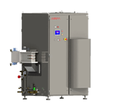
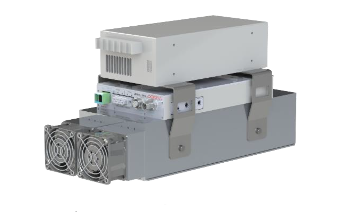
Plasma Sources
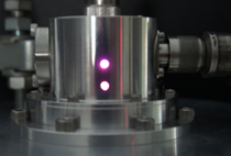
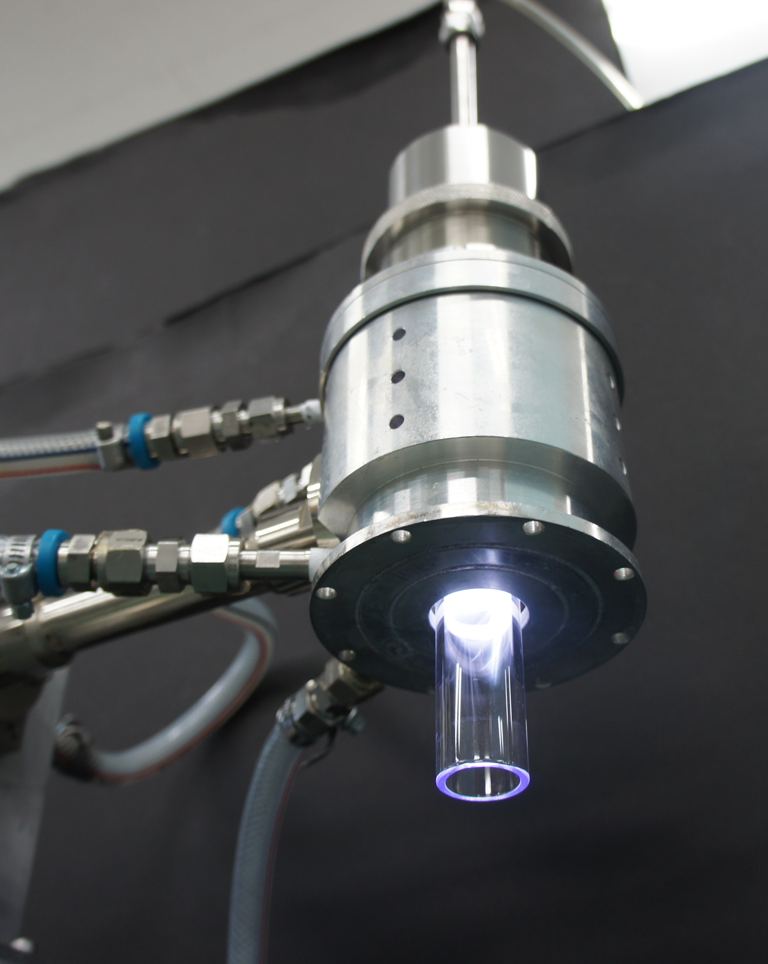 Compact atmospheric pressure microwave plasma source adopts a microwave hybrid mode type resonator developed by fusing the technology of three-dimensional electromagnetic field analysis considering charged particles/plasma and the design technology of high Q high power microwave resonator.
Because power can be supplied by coaxial cable, the setting of the plasma source with high flexibility is enabled, and system constitution with low cost is realized.
Plasma generated under atmospheric pressure is a non-equilibrium plasma, and the low plasma temperature enables plasma processing of the target object while suppressing thermal reactions. Therefore, it is suitable for continuous process (belt conveyor process). In addition, since it is possible to deal with organic matter including ecology, it is expected that a completely new plasma will be applied. In particular, plasma applications in the fields of nanoparticles such as carbon nanotubes, nanotechnology, biotechnology, and medicine have the potential to create new industries.
Applications
- Processing for semiconductor manufacturing(Etching / Ashing / Deposition)
- Desmear processing of via holes on a PCB
- Processing of liquid crystal panels
- Surface modification of polyimide and epoxy materials
- Reduction processing of metal materials
- Washing after plating
- Increasing of junction strength
- Film processing
- Surface modification of lenses
- Nano materials e.g. carbon nanotubes
- Nano particle synthesis
- Sterilization and washing
- Nano particle inactivation
- Nano particle composition
- Thin film deposition
- Organic compound composition
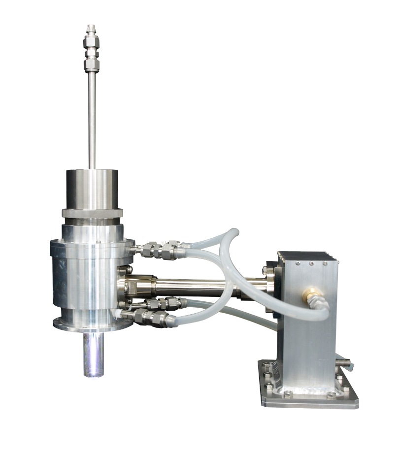
Cavity Type Plasma Source
Features
- Atmospheric pressure
- Reduced pressure
Applications
- Thin film deposition
- Etching
- Spectral analysis
- Sterilization treatment
- Hydrophilic treatment
Specifications
| Model | APLC024-015/141 |
|---|---|
| Operating Frequency | 2450MHz |
| Input Power | 300W-1kW |
| Pressure Range | 300Pa-Atmospheric |
| Gas | Ar |
| Cooling | Water cooling |
| Plasma Spout Diameter | APCL024-015(φ20mm) APCL024-141(φ10mm) |
| Connector | WR430 or WR340 |
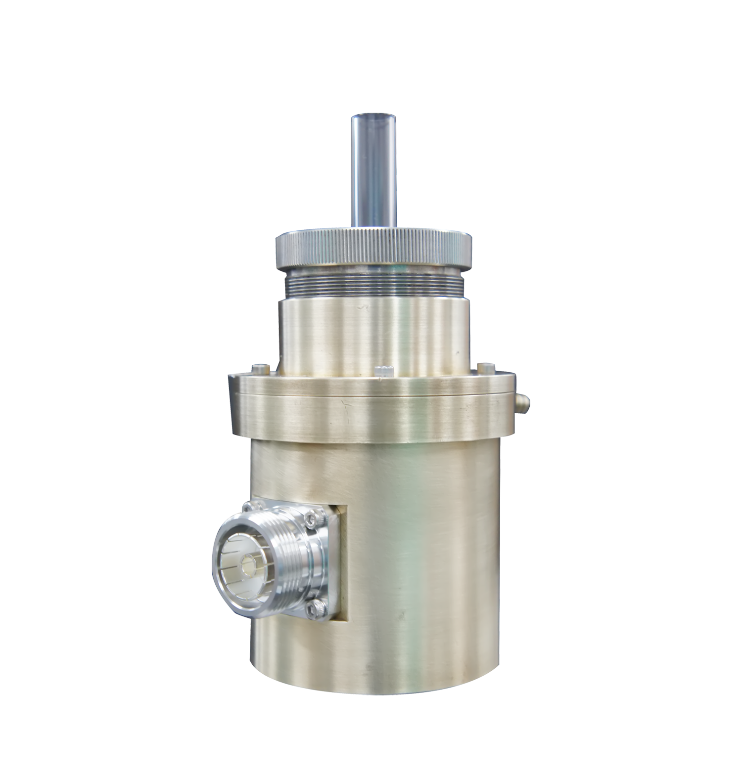
Specifications
| Model | APLC024-359 |
|---|---|
| Operating Frequency | 2450MHz |
| Input Power | 100W-300W |
| Pressure Range | 300Pa-Atmosheric |
| Gas | Ar |
| Cooling | Water cooling |
| Plasma Spout Diameter | φ10mm |
| Connector | 7/16 Connector |
Connection diagram
|
APLC024-015
APLC024-141 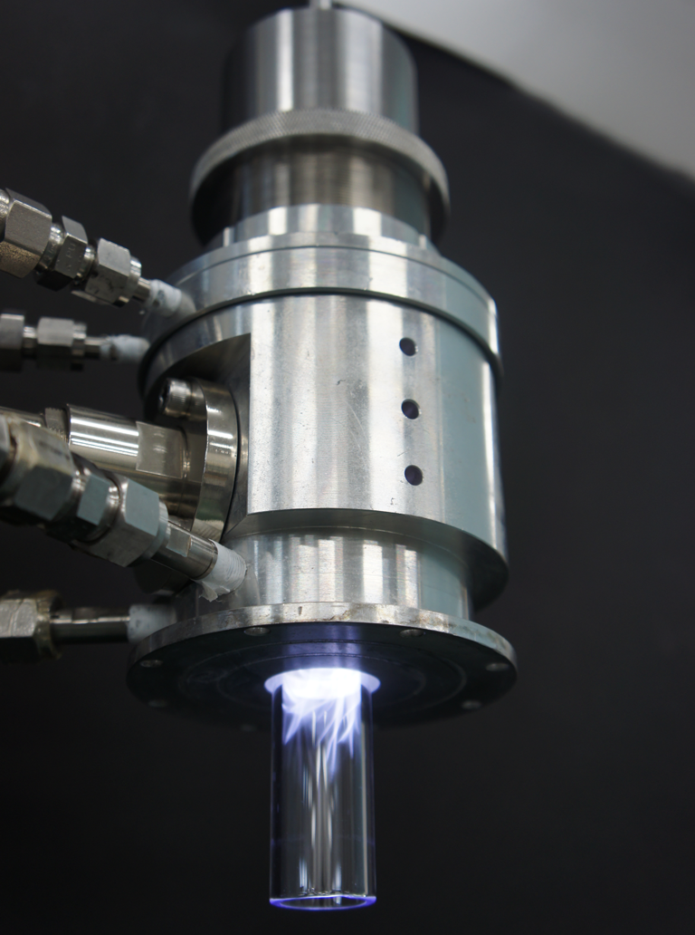
|
Waveguide WR430 or WR340 |
Stub Tuner
WR340 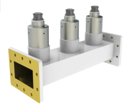 |
Waveguide WR340 |
Magnetron Generator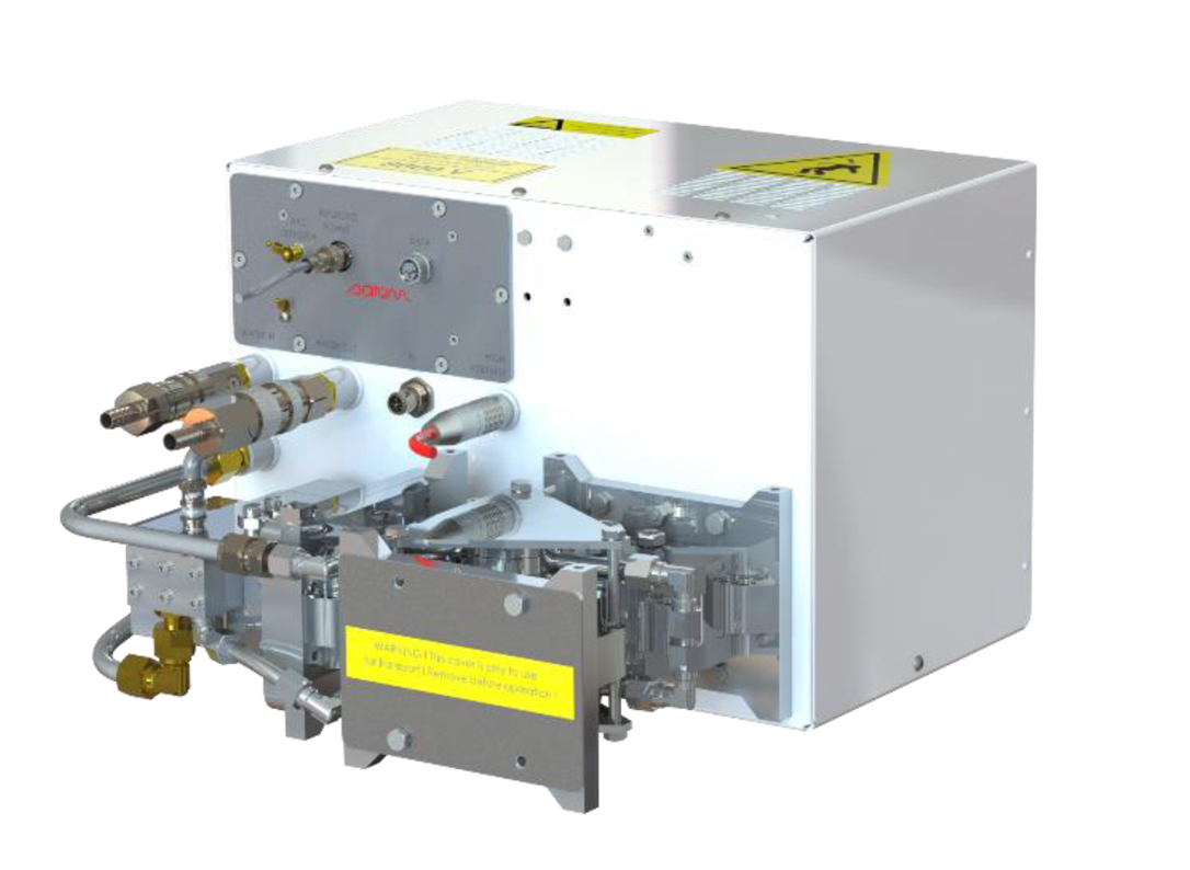
|
|
APLC024-359
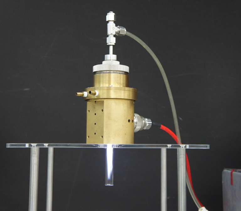
|
Coaxial Cable
7/16-7/16 |
Stub Tuner 7/16 | Coaxial Cable 7/16-N |
Solid State Generator 200W 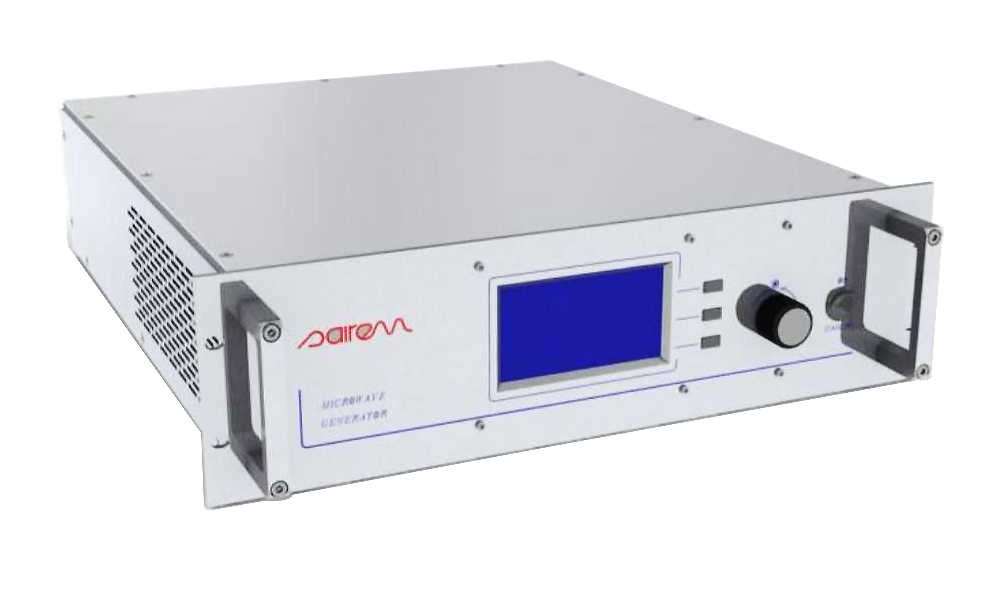 |
||||
|
Coaxial Cable 7/16-7/16 |
Solid State Generator 450W  |
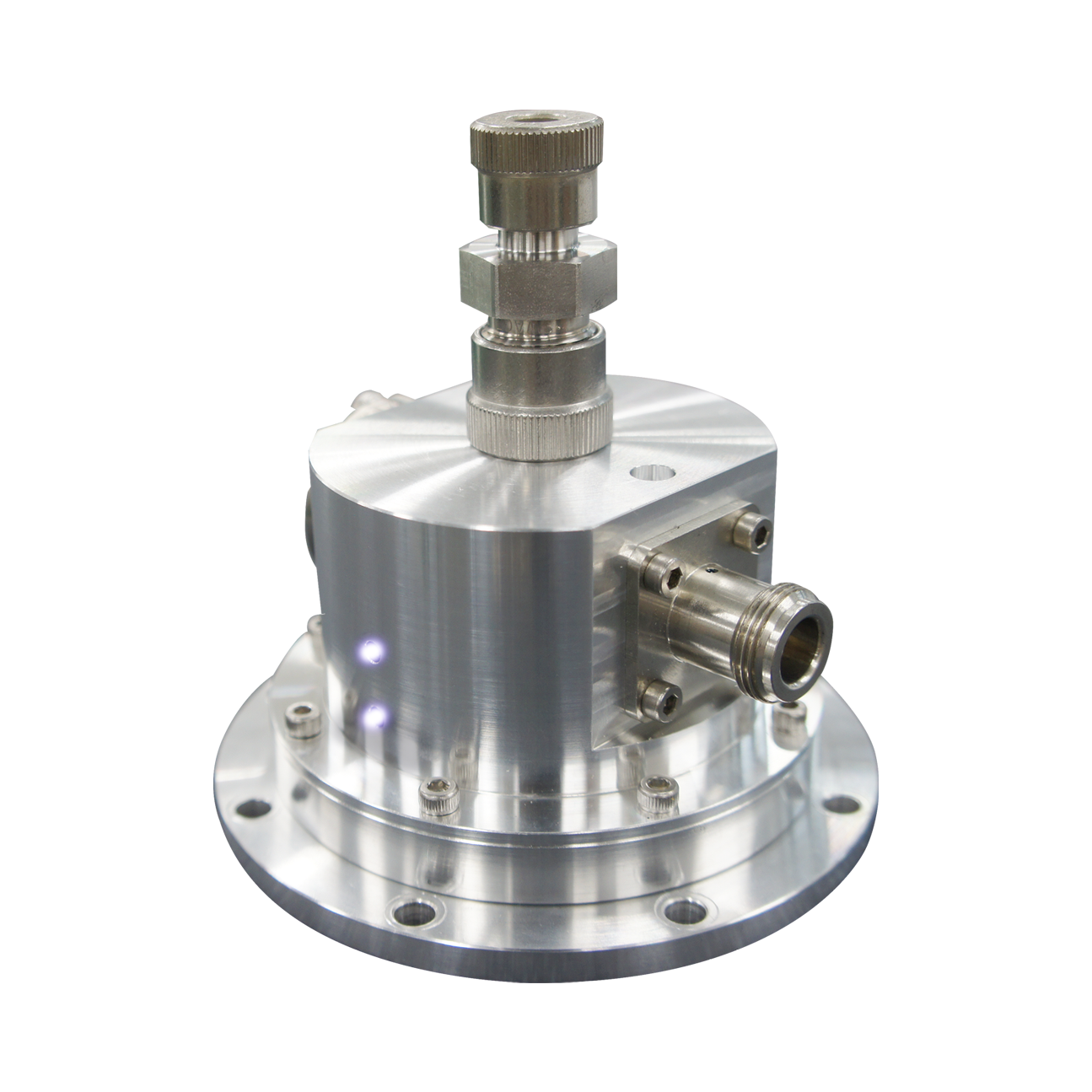
Reentrant Type Plasma Source
Features
- Low power
- Small size
- Easy to install in vacuum chamber
Applications
- Thin film deposition
- Etching
- Spectral analysis
Specifications
| Model | APLC024-348 |
|---|---|
| Operating Frequency | 2450MHz |
| Input Power | 50W-100W |
| Pressure Range | 1Pa-Atmosheric |
| Gas | Ar |
| Cooling | Air cooling |
| Plasma Spout Diameter | φ7mm |
| Connector | N Connector |
Connection diagram
 APLC024-348 |
Coaxial Cable N-N |
Stub Tuner N |
Coaxial Cable N-N |
Solid State Generator
200W 
|
High Voltage Pulse Power Supplies
Diversified Technologies, Inc. is the developer and marketer of high voltage, high power pulse modulators, DC power supplies and control systems. High voltage power supplies offer advanced high voltage power conditioning for demanding research and manufacturing applications.
DTI incorporates the latest advances in solid-state switching technology into efficient, compact, inverter and buck regulator designs. High efficiency and a small footprint mean DTI power supplies can significantly reduce facilities and utility costs.
Microwave Coax Cables
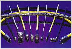
Microwave Coax cables manufactured by Insulated Wire Inc., are world-class cables known from its stability and credibility. These are capable of wide-band frequency up to 60 GHz, low pass and phase stable characteristic. Their products satisfy the needs of the customers, and are widely utilized in microwave measurements systems and microwave communication systems.
Features
- Accurate
- Easy to operate
- No necessity of network analyzer
Currently three measurement methods are provided, and each one has its own feature.
System ConfigurationNetwork Analyzers
Vector Network Analyzer
Our measurement system is compatible with various network analyzers.
(Keysight Technologies /ANRITSU / Rohde & Schwarz / Copper Mountain)
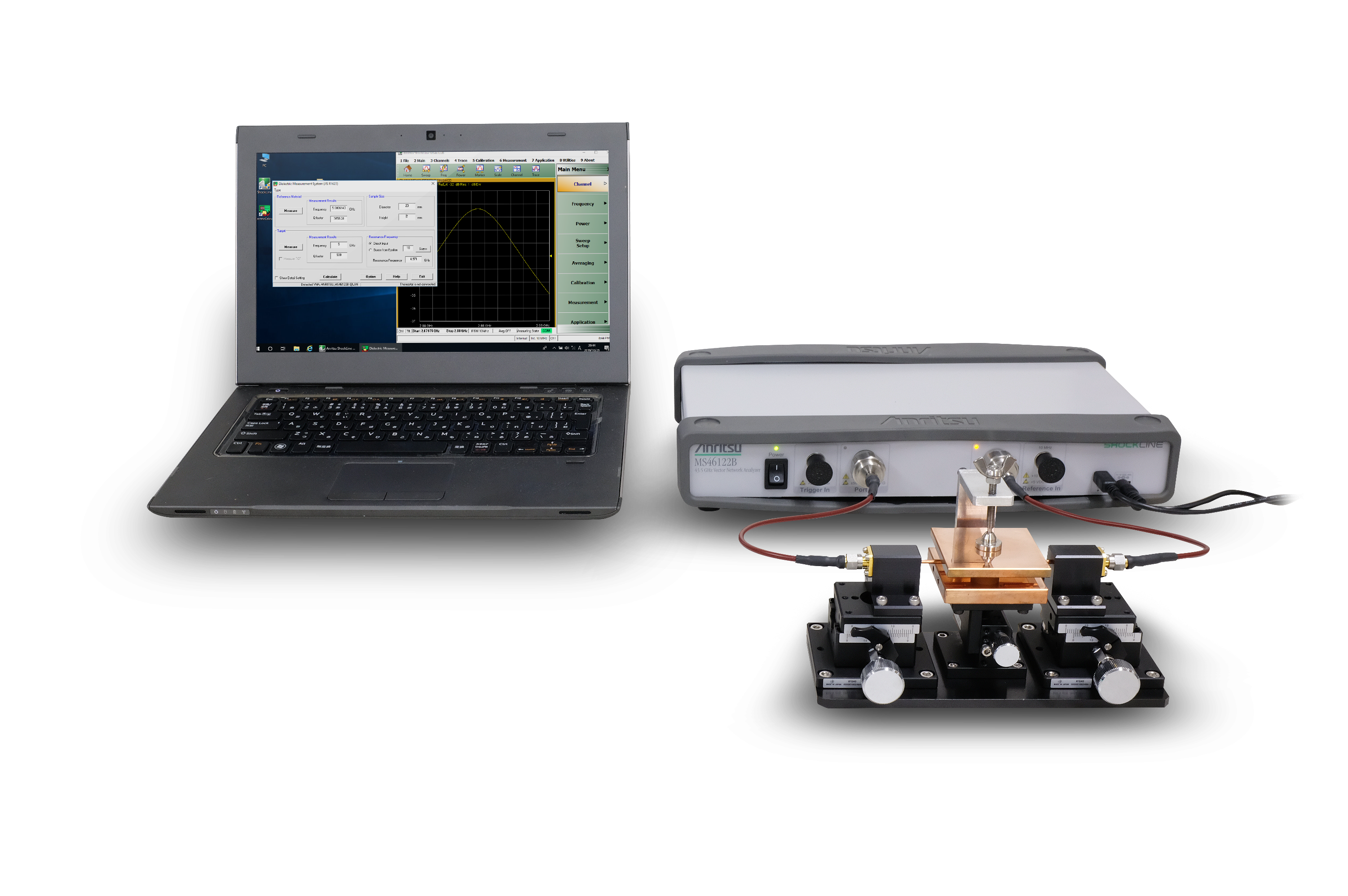
The measurement software controls the network analyzer with optimal parameter, no operation experience is required for stable and high accuracy measurement.
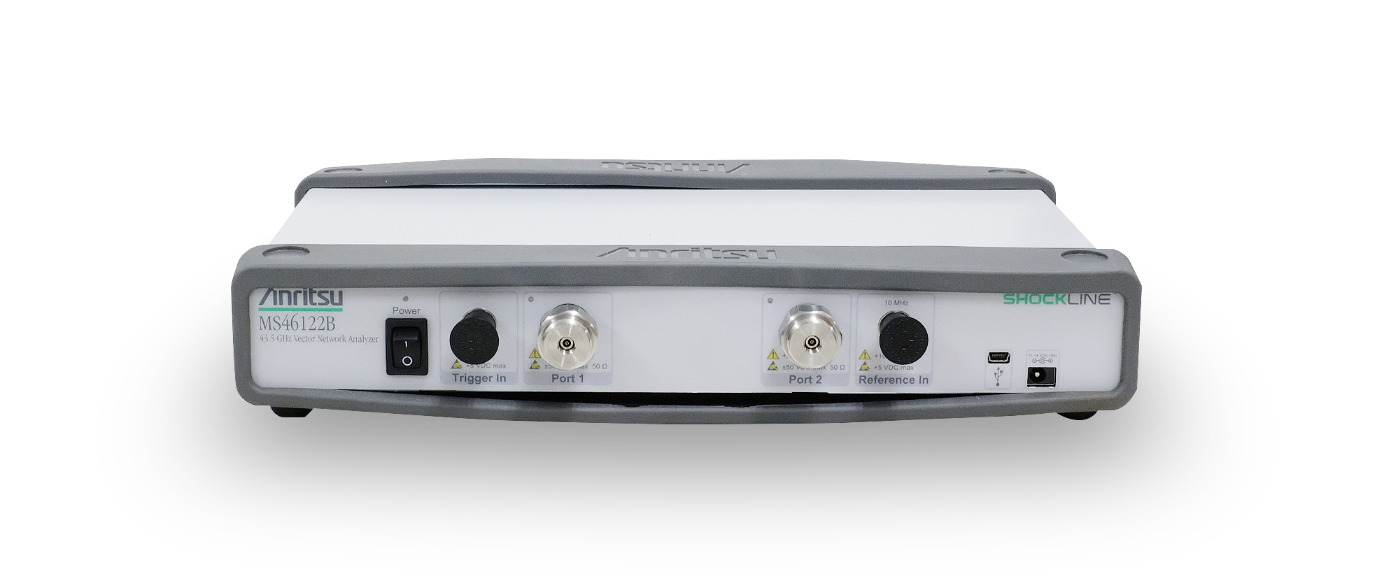
Compact USB Vector Network Analyzer MS46122B
- MS46122B-010 (1MHz~8 GHz)
- MS46122B-020 (1MHz~20 GHz)
- MS46122B-043 (1MHz~43.5 GHz)


ANRITSU ShockLine™ VNA Series MS46122B is a PC controlled compact USB vector network analyzer. One of the most suitable for this system as a new generation VNA that combines low cost and high accuracy.
The dielectric measurement system consists of, 1. Resonator 2. Vector Network Analyzer (VNA), and 3. Windows PC.
Dielectric Measurement Service
We offer the reliable measurement services by utilizing most suitable measurement method according to your specification (material kind, size and shape, frequency)Use
Suitable for measuring the following samples.- Smart Phone case
- Molding plastics
- etc.
Specifications
| Frequency range (5 discrete frequency points / resonator ) |
Type A | 0.8 / 2.45 / 4.2 / 5.8 / 7.6GHz |
|---|---|---|
| Type B | 1 / 3.1 / 5.2 / 7.3 / 9.4GHz | |
| Type C | 2 / 6.1 / 10.2 / 14.3 / 18.4GHz | |
| Measurement range | εr(Dk):1 - 15 tanδ(Df):0.1 - 0.001 | |
| Measurement accuracy | εr(Dk):±1% tanδ(Df):±5% | |
| Sample shape | Arbitrary shape with at least one flat surface. 10mm x 10mm x 0.5mm or larger |
|
This device was developed in cooperation with Maeda Laboratory of Graduate School of The University of Tokyo. PATENT No. 3691812
Measurement using evanescent wave
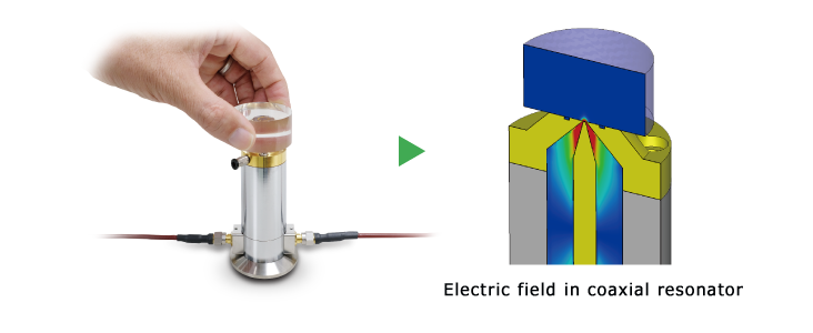
The near field called the evanescent wave leaking from the small opening of the open coaxial resonator penetrates in the measurement sample, and the resonance characteristics change depending on the dielectric properties of the sample.
[Caution]
This resonator measures the dielectric properties at a local area near the surface of the measurement sample.
The measurement target must be of uniform composition. If the layered materials or composite materials such as printed circuit boards are measured, the results will be influenced by the material properties at the surface of the sample.
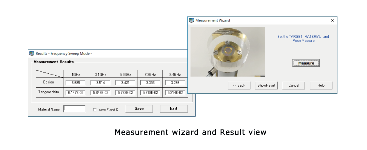
Simple operation by Easy-to-use Software
AET’s measurement software is designed to use intuitively without any expert knowledge about dielectric measurements or microwave electronics.
FAQ
General
Q1. What is the open coaxial resonator type microwave dielectrometer ?
Q1. What is the open coaxial resonator type microwave dielectrometer ?
A1.
The open coaxial resonator type microwave dielectrometer is the system which measures dielectric properties at microwave frequencies. This system has 2 types, which use either a synthesized sweep oscillator (an alternative to a network analyzer) or a network analyzer.
Q2. What are the system components of the synthesized sweep oscillator type and the network analyzer type?
A2.
The synthesized sweep oscillator type consists of an oscillator, which includes a microwave signal generator and a detector, a measurement probe, a customized software, and accessories. This is a low cost type because it does not have expensive measurement devices. The network analyzer type sets up with your network analyzer to use. It consists of a measurement probe, a customized software, and accessories.
(*Please see the movie titled "2.System Components" on the top page.)
Q3. What is the difference between this system and the conventional system?
Q3. What is the difference between this system and the conventional system?
A3.
The strongest point of the microwave dielectrometer is its ease of use. This system enables fast and non-destructive measurement of dielectric materials, because the probe can handle materials of any shapes as long as there is one flat surface. In addition, the microwave dielectrometer has highly accurate measurement software. By simply placing the material on the surface of the probe, and following an easy step-by-step operation of the software wizard, the measurement is achieved for complex dielectric properties very accurately and very simply. (*Please see the movies titled "1.AET Microwave Dielectrometer" and "4.Actual Measurement" on the top page.)
Q4. What is the difference between this system and the conventional system?
Q4. What is the difference between this system and the conventional system?
A4.
The tool to measure is a unique measurement probe called a "coaxial resonator"(PATENT No.3691812). The measurement can be chosen at a five-point simultaneous measurement mode or single-frequency measurement mode.
Type1: 0.8/2.45/4.2/5.8/7.6GHz Type2: 1/3/5/7/9GHz
Type3: 2/6/10/14/18GHz
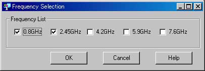
Choose the specific frequency from the "frequency setting" list.
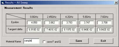
The result of 5-points simultaneous measurement
(*Please see the movie titled "3.Open Coaxial Probe" on the top page.)
Q5. What is the measurement principle using this probe?
Q5. What is the measurement principle using this probe?
A5.
If a sample material is placed on the probe, the evanescent electrical field leaks from the probe tip into the sample material. This electrical field changes with the dielectric properties of the material, which in turn changes the resonant frequency and the Q factor of the whole cavity. The dielectric properties (εr, tanδ) are then calculated from the changed resonance.
(*Please see the movie titled "3.Open Coaxial Probe" on the top page.)
Q6. How good is the accuracy and what is important for accurate measurements?
Q6. How good is the accuracy and what is important for accurate measurements?
A6.
The random error of the epsilon is estimated to be less than 1%, and the error of the tangent delta is less than 5%. The absolute accuracy will be confirmed by the reference materials. Two different materials are used as references. By calculating the relative difference between the measurement results of the references and a sample material, external error sources (eg.room temperature) are eliminated. Most important for accurate measurements is a firm contact between the sample material and the surface of the coaxial probe. Only a tiny gap might significantly change measurement results. Microwave Dielectrometer has a vacuum absorption attachment equipped on the probe tip. The sample contacts with the probe firmly and the stable and accurate measurement is possible. (*Please see the movie titled "1.AET Microwave Dielectrometer" on the top page.)
Materials to be tested
Q1. What are the requirements for the sample material?
Q1. What are the requirements for the sample material?
A1.
The materials to be tested are required to have at least one flat and smooth surface (larger than 10mm × 10mm). The sample shape is arbitrary and the sample dimension should be larger than 10mm × 10mm × 0.5mm. To measure thin film materials, the film have to be stacked to get a total thickness greater than 0.5mm.
Q2. What are the limitations of the dielectric properties?
Q2. What are the limitations of the dielectric properties?
A2.
This system can measure relative dielectric constants from 1 to 15, and the loss tangent from 0.001 to 0.1.
Q3. What is the reason of the limitation of the properties?
Q3. What is the reason of the limitation of the properties?
A3.
The evanescent field does not penetrate deep enough into high epsilon materials, which makes an accurate measurement of the dielectric constant difficult. For small loss tangent, the total loss of the probe is relatively higher than the conventional cavity resonator because of the leakage of the evanescent field. This is the main reason for the difficulty of measuring very small dielectric losses. We recommend the resonant cavity type microwave dielectrometer for the measurement of the sample with high epsilon and very small dielectric losses.
Q4. Is it possible to measure anisotropic materials?
Q4. Is it possible to measure anisotropic materials?
A4.
The evanescent field vector is not uniform. Thus, the anisotropic properties can not be measured.
Q5. Is it possible to try sample measurements?
Q5. Is it possible to try sample measurements?
A5.
Yes. Please send your sample materials. We will send you the measurement results.
contact:info@aetjapan.com
System Option
Q1. What are the reference materials?
Q1. What are the reference materials?
A1.
Microwave Dielectormeter uses the two different reference materials with well known dielectric properties. By calibrating the measurement parameters with these materials, this system achieves a quantitative accuracy. We use the two single crystals of SiO2 and MgO as the reference materials.
Q2. Which network analyzers can be used for the microwave dielectrometer?
Q2. What are the limitations of the dielectric properties?
A2.
Keysight Technologies PNA series, ENA series, 872x series, ANRITSU 37000 and Rohde & Schwarz network analyzers. If you have any other network analyzers, please contact us.
contact:info@aetjapan.com
Use
Suitable for measuring the following samples.- PCB substrates
- Thin films
- Plastics
- Ceramics
Specifications
| Frequency range | 1GHz - 10GHz |
|---|---|
| Frequency point | 1 frequency point per a resonator |
| Measurement range | εr(Dk):1 - 30 tanδ(Df):0.1 - 0.0001 |
| Measurement accuracy | εr(Dk):±1% tanδ(Df):±5% |
| Sample shape | Strip, larger than 80mm (L) × 3mm (W) × 0.05mm - 1mm (T) |
| Compliant standard | JIS C2565, ASTM D2520 |
Feature: TM mode Cavity Resonator
TM mode cavity resonator uses the TM resonant mode (TM010 / 011), where the electric field vector is parallel to the rotational axis of the cylindrical cavity.
By inserting the measurement sample along with the center axis of the cylinder, the resonance changes according to its dielectric constant.
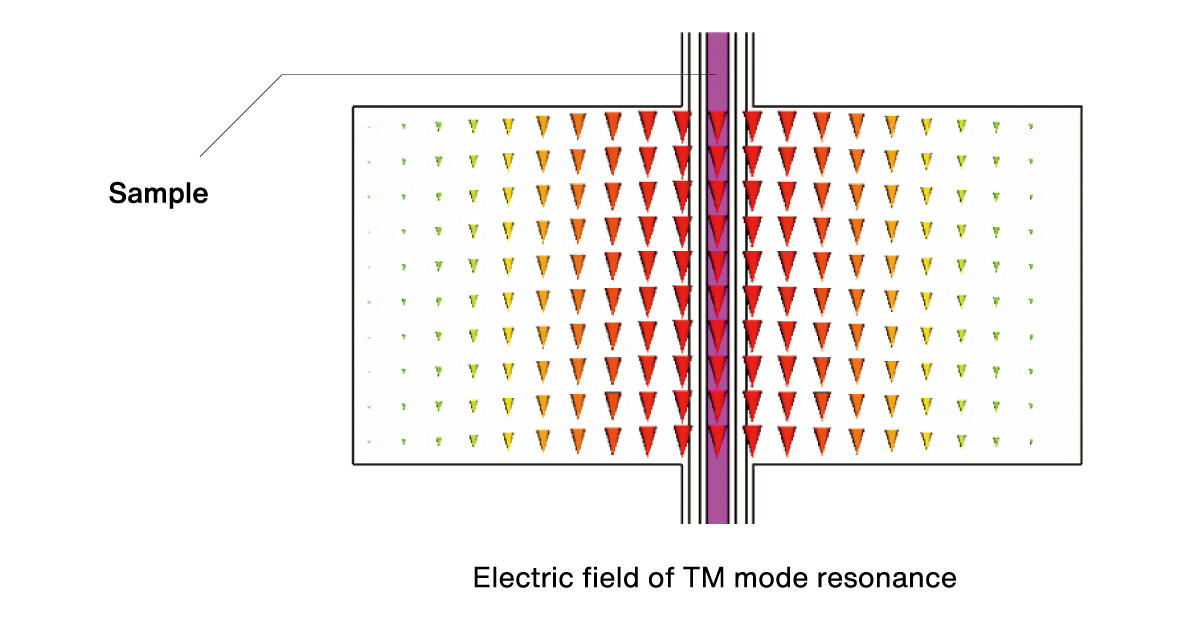
Shape and size of sample
The shape of the measurement sample is a strip. The dielectric constant in the longitudinal direction of the strip is measured.

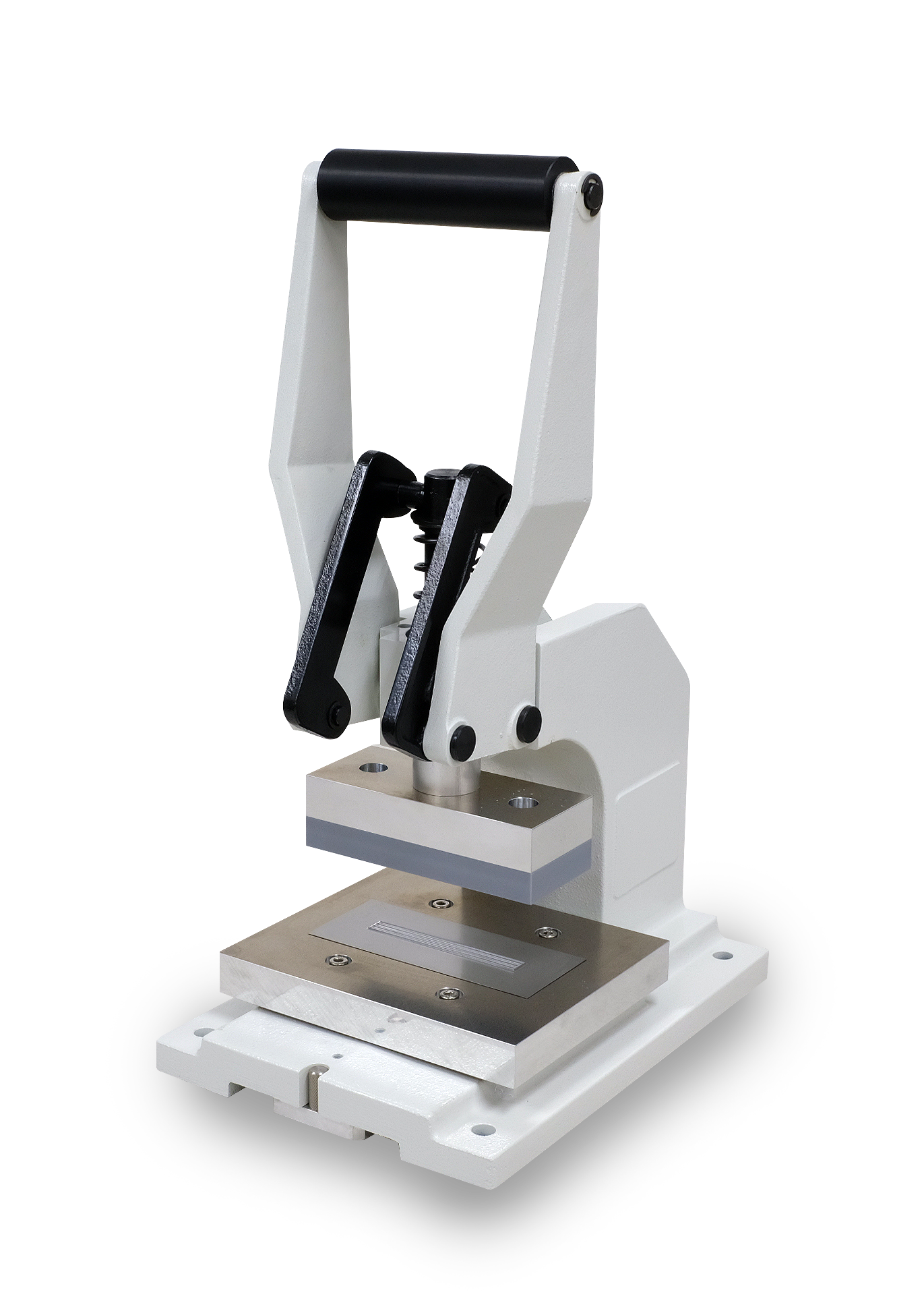
Cutting machine for film (Optional Item)
The dedicated cutting machine is available for film materials (thickness is 0.2mm or less).
FAQ
General
Q1. What is the resonant cavity type microwave dielectrometer ?
Q1. What is the resonant cavity type microwave dielectrometer ?
A1.
The resonant cavity type microwave dielectrometer is the system which measures dielectric properties at microwave frequencies. This system has 2 types, which use either a synthesized sweep oscillator (an alternative to a network analyzer) or a network analyzer.
Q2. What are the system components of the synthesized sweep oscillator type ( an alternative to a network analyzer ) and the network analyzer type ?
A2.
The synthesized sweep oscillator type consists of an oscillator, which includes a microwave signal generator and a detector, a measurement cavity, a customized software, and accessories. This is a low cost type because it does not have expensive measurement devices. The network analyzer type sets up with your network analyzer to use. It consists of a measurement cavity, a customized software, and accessories.
Q3. What is the measurement theory of this system?
Q3. What is the reason of the limitation of the properties?
A3.
The measurement is based on the resonant-perturbation method. The resonant characteristic of the cavity, the resonant frequency and the quality factor will be changed when the material is inserted into the cavity. The complex permittivity can be calculated by the change of the resonance frequency and Q factor.
Q4. What is the difference between this system and the conventional system ?
Q4. What is the difference between this system and the conventional system ?
A4.
The resonant cavity type microwave dielectrometer has highly accurate measurement software. By simply inserting a material into the slot of the cavity, and following an easy step-by-step operation of the software wizard, the measurement is achieved for complex dielectric properties very accurately and very simply.
( *Please see the movie titled "4.Actual Measurement" on the top page. )
Q5. What is the tool to measure ?
Q5. What is the tool to measure ?
A5.
The tool to measure is a resonant cavity which has single-frequency point per a resonator. It is suitable to measure for thin films, multilayer structure materials, ceramics, liquid, various resin and powder. The measurement method was established by JIS (Japanese Industrial Standards) C 2565.
Q6. How good is the accuracy ?
Q6. How good is the accuracy ?
A6.
The random error of the epsilon is estimated to be less than 1%, and the error of the tangent delta is less than 5%.
Materials to be tested
Q1. What are the requirements for the sample material ?
Q1. What are the requirements for the sample material ?
A1.
The measurement method by the resonant cavity is destructive measurement. The dimension of the sample to be tested should be larger than 80mm (L) × less than 3mm(W). Thickness is 0.05mm - 1mm.
Q2. What are the limitations of the dielectric properties ?
Q2. What are the limitations of the dielectric properties ?
A2.
This system can measure relative dielectric constants from 1 to 30, and the loss tangent from 0.0001 to 0.1.
Q3. Is it possible to try sample measurements ?
Q3. Is it possible to try sample measurements ?
A3.
Yes. Please send your sample materials. We will send you the measurement results.
contact:info@aetjapan.com
System Option
Q1. Which network analyzers can be used for the microwave dielectrometer?
Q1. Which network analyzers can be used for the microwave dielectrometer?<
A1.
Keysight Technologies PNA series, ENA series, 872x series, ANRITSU 37000 and Rohde & Schwarz network analyzers. If you have any other network analyzers, please contact us.
contact:info@aetjapan.com
Use
Suitable for measuring the following samples.- Materials for 5G
- Flexible substrate
- etc.
Specifications
| Frequency range | 10GHz - 40GHz |
|---|---|
| Frequency point | 1 frequency point per resonator |
| Measurement range | εr(Dk):1 - 5 tanδ(Df):0.01 - 0.0001 |
| Measurement accuracy | εr(Dk):±1% tanδ(Df):±5% |
| Sample shape | Sheet (Thickness is less than 0.3mm) |
| Compliant standard | JIS R1641, IPC-TM650 2.5.5.13 |
Feature: TE mode Cavity Resonator
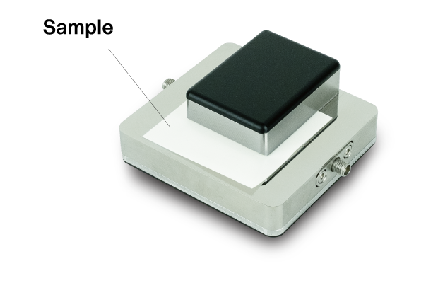
TE mode cavity resonator uses the TE resonant mode (TE011), where the electric field vector is circulating around the rotation center axis of the cylindrical cavity.
This mode is maintained even when the cavity is separated up and down, therefore it enables measurement by inserting a sheet-shaped sample.
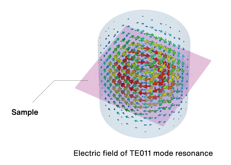
Shape and size of sample
TE mode cavity resonator uses the TE resonant mode (TE011), where the electric field vector is circulating around the rotation center axis of the cylindrical cavity.
This mode is maintained even when the cavity is separated up and down, therefore it enables measurement by inserting a sheet-shaped sample.

This method has high resolution for loss and is suitable for low loss film measurement.
The measurement direction of the dielectric constant is in-plane.
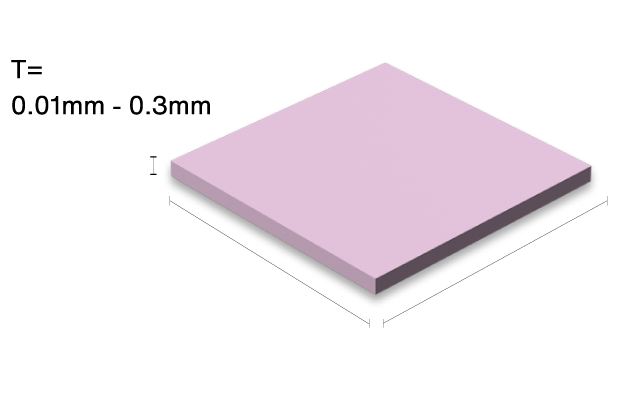
| Size in plane | 10GHz | ≥50mm |
| 20GHz | ≥40mm | |
| 28/40GHz | ≥30mm |
Dielectric Resonator for Ceramics
This system is designed for low loss dielectrics with high dielectric constant.
Dielectric cylinder sample is short-circuited at both ends by parallel conducting plates.
The dielectric cylinder resonates in TE011 mode by microwave feeding with loop antenna.
Specifications
| Measurement frequency | Lower than 20GHz (Frequency depends on size and dielectric properties of sample) |
|---|---|
| Measurement range | εr(Dk):5 - 200 tanδ(Df):0.001 - 0.00001 |
| Measurement accuracy | εr(Dk):±1% tanδ(Df):±5% |
| Sample shape | Cylinder |
| Compliant standard | JIS R1627, IEC 61338-1-3 |
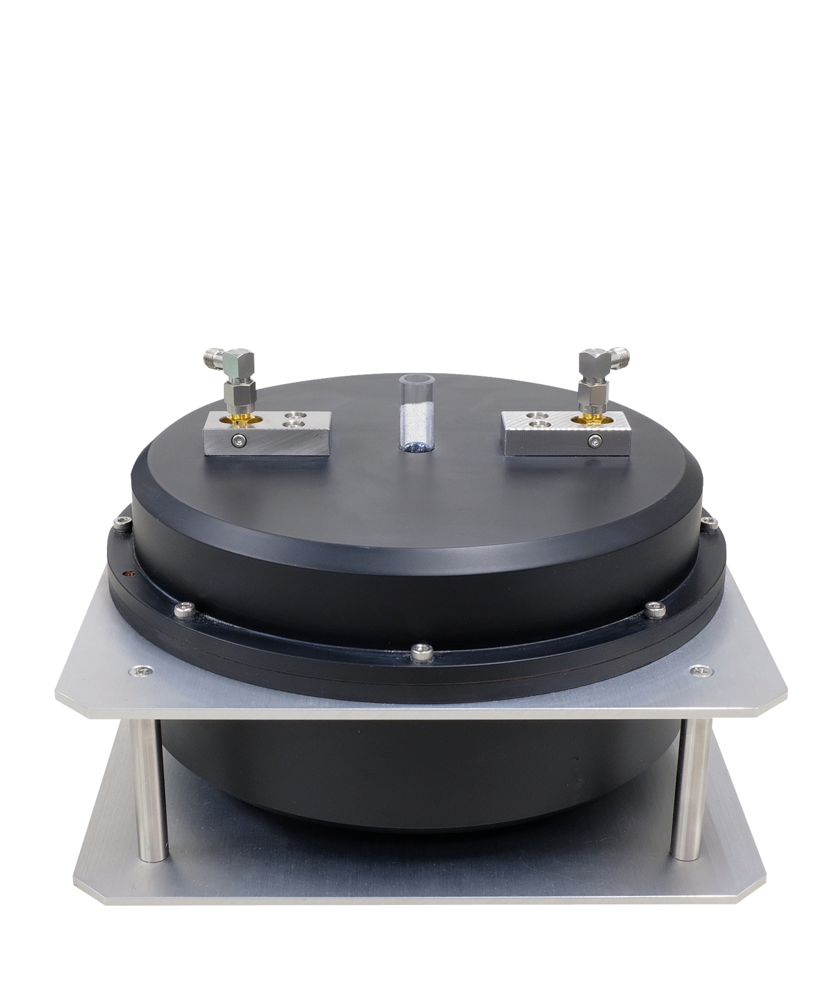
Cavity Resonator for Powder
Powder samples can be measured by loading into the quartz tube.
The system calculates the dielectric constant of the powder itself by the volume filling rate from the true density of the sample.
This system also supports accurate measurement of non-polar solvents with low dielectric constant and low dielectric loss.
Dedicated vibrator enables dense filling of powder samples.
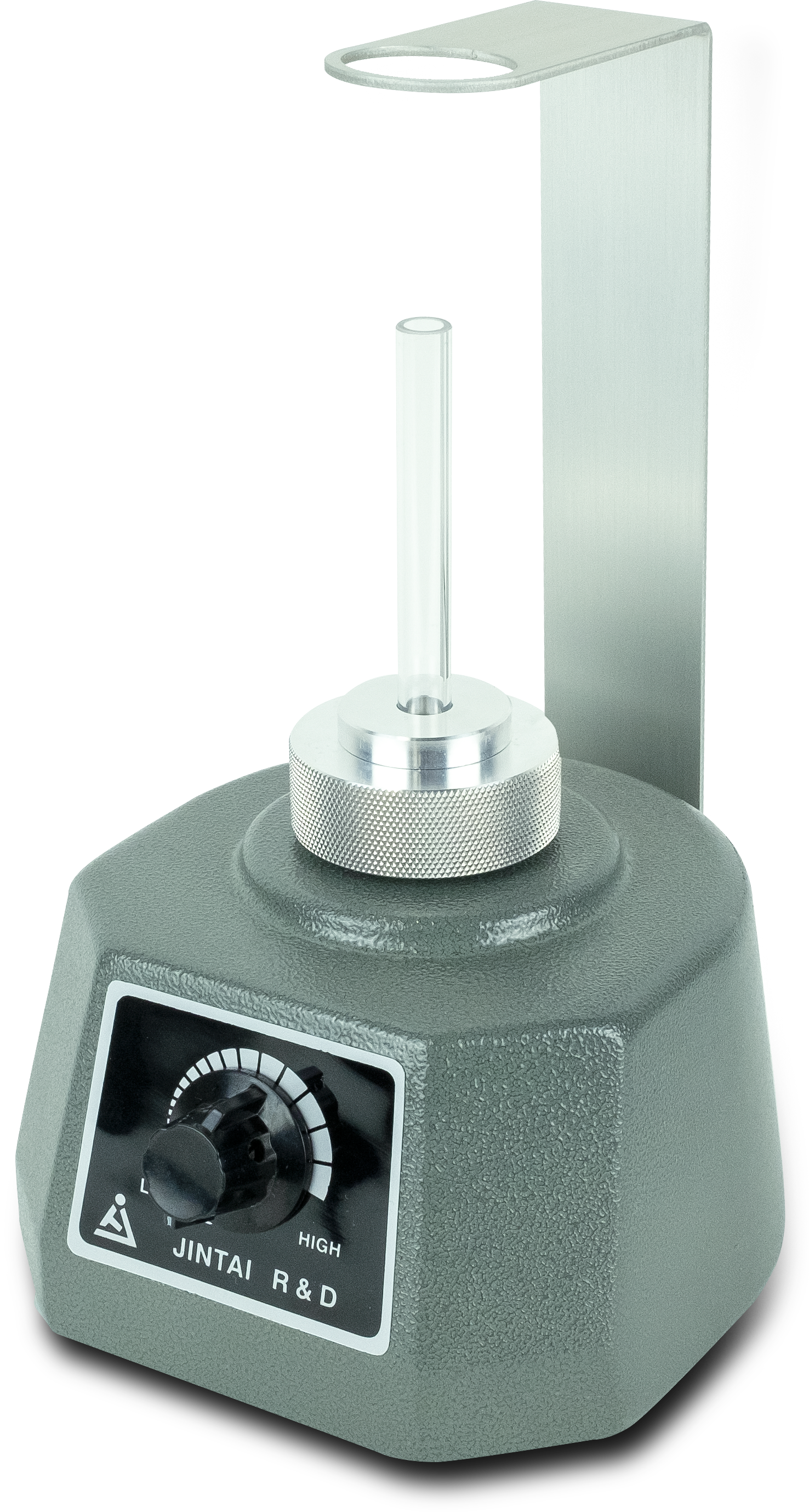
Specifications
| Frequency range | 1GHz (Ask for other frequencies) |
|---|---|
| Sample form | Powder, Liquid |
| Measurement range(Volume averaged) | εr(Dk):1 - 6 tanδ(Df):0.01 - 0.0001 |
| Measurement accuracy | εr(Dk):±1% tanδ(Df):±5% |
| Required amount | more than 3 cc (for 1GHz) |
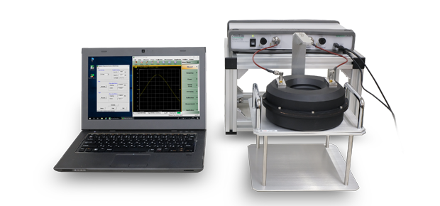
Cavity Resonator for Cables
The dedicated resonator enables the high-resolution measurement for the low-loss insulation materials in the form of cable (ex. Foamed PTFE).
The special design makes it easy to set up soft cable insulators
※Please contact for details.
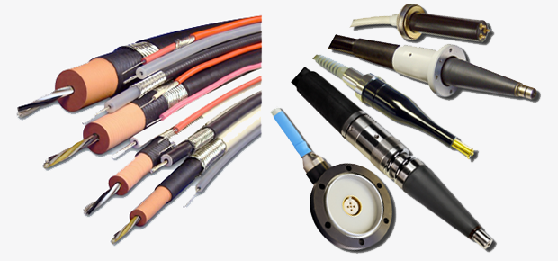
High Voltage Cable
High Voltage Termination, Feed-Through Bushing
Cavity Type Plasma Source
Features
- Atmospheric pressure
- Reduced pressure
Applications
- Thin film deposition
- Etching
- Spectral analysis
- Sterilization treatment
- Hydrophilic treatment

Specifications
| Model | APLC024-015/141 |
|---|---|
| Operating Frequency | 2450MHz |
| Input Power | 300W-1kW |
| Pressure Range | 300Pa-Atmospheric |
| Gas | Ar |
| Cooling | Water cooling |
| Plasma Spout Diameter | APCL024-015(φ20mm) APCL024-141(φ10mm) |
| Connector | WR430 or WR340 |

Specifications
| Model | APLC024-359 |
|---|---|
| Operating Frequency | 2450MHz |
| Input Power | 100W-300W |
| Pressure Range | 300Pa-Atmosheric |
| Gas | Ar |
| Cooling | Water cooling |
| Plasma Spout Diameter | φ10mm |
| Connector | 7/16 Connector |
Connection diagram
|
APLC024-015
APLC024-141 
|
Waveguide WR430 or WR340 |
Stub Tuner
WR340  |
Waveguide WR340 |
Magnetron Generator
|
|
APLC024-359

|
Coaxial Cable
7/16-7/16 |
Stub Tuner 7/16 | Coaxial Cable 7/16-N |
Solid State Generator 200W  |
||||
|
Coaxial Cable 7/16-7/16 |
Solid State Generator 450W  |
Gun Driver / Magnetron Modulator
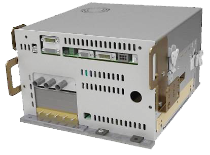
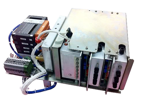
Founded in 1973, ETM is trusted by leading system integrators worldwide for Tailored Power Subsystems and Systems. ETM’s unique value could be recognized in the 2MeV - 15MeV X-ray market. They are the only company in the world that engineer and manufacture all subsystems required for linac systems. For example, they have developed specialized linac gun modulation products that meet the detailed control requirements of customers in medical and security markets.
Reentrant Type Plasma Source
Features
- Low power
- Small size
- Easy to install in vacuum chamber
Applications
- Thin film deposition
- Etching
- Spectral analysis

Specifications
| Model | APLC024-348 |
|---|---|
| Operating Frequency | 2450MHz |
| Input Power | 50W-100W |
| Pressure Range | 1Pa-Atmosheric |
| Gas | Ar |
| Cooling | Air cooling |
| Plasma Spout Diameter | φ7mm |
| Connector | N Connector |
Connection diagram
 APLC024-348 |
Coaxial Cable N-N |
Stub Tuner N |
Coaxial Cable N-N |
Solid State Generator
200W 
|
Power Supplies for Capacitor Charging
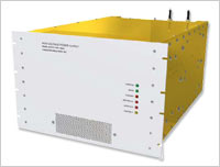
Stangenes Industries has developed several advanced capacitor charging technologies. The state-of-the-art power conversion units utilize IGBT switches operating at high frequency in a quasi-resonant design utilizing zero voltage switching topology. These units often contain no oil or other dielectric fluids, so these units are significantly lighter and more reliable than comparable units. The advanced Optimized Charging Cycle (OCC) that we have developed reduces the peak power consumption from the line. This feature enables charging of large capacitor banks without exceeding the allowed average power.
System Configuration
The components of the Probe Station System can be customized according to the user's specifications. Special discounted prices can be available if an Agilent network analyzer and Probe Station are purchased as a system.
| Standard Configuration |
|---|
| Probe Station |
| Vacuum Pen and Vacuum Pump |
| Options |
| Network Analyzer ( Agilent Technologies,Inc ) |
| RF lZl Probe ( Cascade Microtech,Inc ) |
| Active Differential Probe and Probe Amplifier ( Agilent Technologies,Inc ) |
| 4-terminal DC Measurement Needle ( Tungsten needle ) |
| Vibration Isolation Table/Desk |
Magnetron Microwave Generators

| Frequency | Power | Model | ◎:CW&Pulse(Option) ○:CW | Manufacturer | |
|---|---|---|---|---|---|
| 2kW | GMP 20 K | ◎ | Sairem | ||
| 3kW | GMP 30 K | ◎ | Sairem | ||
| 6kW | GMP 60 K | ◎ | Sairem |
| Frequency | Power |
|---|---|
| 36kW | GLP 360 |
| 54kW | GLP 540 |
| 75kW | GLP 750KI |
| 100kW | GLP 1000KI |
Specifications
Model: AGPS501-002
| Frequency | Depending on specifications of probes. |
|---|
[Probing Stage]
| Measurement Table | Movement (Coarse Adjustment) X: Fixed Y: 125mm (Sliding type) Z: Up and down type Movement (Fine Adjustment) Z: ±6.5mm (10μm Scale interval) θ : ±5° Measurement Table Size: Max 255mm × 100mm Measurement Sample Size: Up to 190mm × 100mm |
|---|
[Micropositioner]
| Positioner | (Fine adjustment) Movement direction X: ±6.5mm Y: ±6.5mm Z: ±6.5mm (10μm scale intervals) θ : ±3 degrees |
|---|---|
| Positioner Table | Movement direction X: 105mm Y: 52.5mm (2.5mm per ratchet step) Z: fixed |
[Probe]
| Probe Type | Air coplanar, semi-rigid or differential active probe |
|---|
[Stereo Microscope]
| Olympus Model SZ61 or equivalents | Magnification: 0.67 - 4.5X Zoom Ratio: 6.7 Operation Range: 110mm Lens: WHSZ10 x-H |
|---|
[Main Unit]
| Size and Weight | 600mm(W) × 400mm(D) × 550mm(H), 27kg |
|---|
[Vacuum Pen and Vacuum Pump]
| Vacuum Pen | Pad Diameter: Φ6mm Suction Strength: 94g (max) |
|---|---|
| Vacuum Pump | Ultimate Vacuum: -33.3kPa { -250mmHg } Discharge Rate: 5 l⁄min Rated Voltage: AC100V (50⁄60Hz) Power Consumption: 15⁄14W Current: 0.35⁄0.3A Rated Time: Continuous |
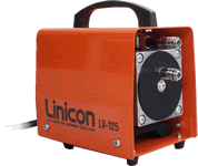
Vacuum Pump
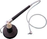
Vacuum Pen
Options
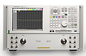
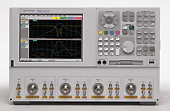
Network Analyzer (Keysight Technologies)
All network analyzers manufactured by Keysight Technologies can be used for the probe station system.

RF lZlProbe ( Cascade Microtech, Inc. )
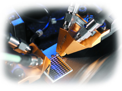
lZlProbe is a registered trademark of Cascade Microtech.
AET, Inc. is a business partner of Cascade Microtech, Inc.
Active Differential Probe and Probe Amplifier (Keysight Technologies, Inc.)
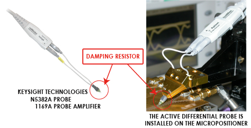
Installation of Active Differential Probe in the Micropositioner
High precision measurement at high frequencies has been limited because general oscilloscope probes are usually handheld. By assembling the 13GHz Active Differential Probe (Keysight) to the Micropositioner, a handsfree active differential probe measurement system was created. Circuit boards equipped with DSPs and CPUs can be easily measured with high stability.
| Bandwidth | Range | Input Impedance |
|---|---|---|
|
|
|

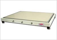
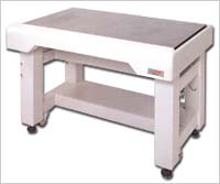
Vibration Isolation Table/Desk
The Vibration Isolation Table/Desk are designed to reduce vibration of the Probe Station to a minimum. They can improve the measurement accuracy and the reproducibility of the Probe Station.
Please see the product catalog for further details.
Dispenser Cathodes
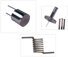
Dispenser cathodes manufactured by HeatWave Labs, Inc. are porous tungsten impregnated with a barium oxide, offering a long life time. High current density is achieved by heating within 950 to 1200℃. Dispenser cathodes can be used in a wide variety of applications such as electron tubes, microwave tubes, accelerators, plasma devices, CRTs, etc.
- Barium impregnated tungsten.
- 950 - 1200℃ operation
- More than 10,000 hours of life time could be achieved.
- 3 - 5 A⁄cm2 CW emission.
- Emission enhancing coatings and impregnants available.
Hollow Cathode Plasma Sources
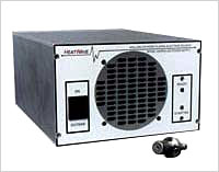
High current, hollow cathode plasma sources manufactured by HeatWave Labs, Inc. can deliver precisely controlled electron currents into plasma environments including corrosive atmospheres. Far superior to other devices, it offers easy starting (no High Voltage), very stable output, continuously variable emission current, low gas flow requirements, lower operating temperature and longer life. The output is free of any metal contaminants, a common problem with high temperature refractory sources.
HWPES-250
- Ion beam neutralization
- Surface charge control
- Electron filament replacement
- Electron enhancement of magnetron and diode discharges
- Arc discharge generators
Solid State Microwave Generators
| Frequency | Power | Model | ◎:CW&Pulse(Option) ○:CW | Manufacturer | |
|---|---|---|---|---|---|
| 2.45GHz | 200W | GMS 200 | ◎ | Sairem | |
| 450W | GMS 450 | ○ | Sairem | ||
| 1000W | GMS 1000 | ○ | Sairem | ||
| module | 200W | KMS 200 | ◎ | Sairem | |
| 250W | KU SG 2.45-250A | ○ | Kuhne | ||
| 450W | KMS 450 | ○ | Sairem |
Model 102248 and 102170 Single Crystal LaB6 cathodes
Features
- Single Crystal LaB6 ( Lanthanum Hexaboride ) emitter
- Directly heated construction
- Can include 102170 flange mount with shield⁄focus electrode
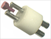
Model 102248-01 Ø2.0mm
Model 102248-01 Ø2.8mm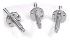
Model 102170 Includes 102248 Cathodes
Klystron Microwave Generators
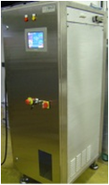
| Frequency | Power | Model | ◎:CW&Pulse(Option) ○:CW | Manufacturer | |
|---|---|---|---|---|---|
| 14GHz | 2.2kW | GKP 22KP | ◯ | Sairem | |
| 18GHz | 2.2kW | GKP 24KP | ◯ | Sairem |
The Micropositioner provides high precision positionings on straight motions of X,Y and Z axes and rotational motion of theta axis. Each axis of X, Y, Z and theta has a micrometer that can be fine-adjusted. A parallel positioning of a probe is performed roughly by rotating the theta axis stage, and is adjusted finely by controlling a micro adjustment. The theta axis provides ±3 degrees of rotational motion. This Micropositioner can be utilized under the severe measurement condition which does not allow even the slightest gap between the probe and a sample to be measured.
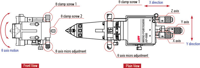
Two types of Micropositioner are available to support air coplanar and multi-needle probes.
Features
- High precision positioning in X-Y-Z-θ axes
- Equipped with an adjustment mechanism in the θ-axis, 360° for coarse adjustment and ±3° for fine adjustment.
- Micrometer adjustment mechanism for the four axes ( X-Y-Z-θ ) so that each axis can be finely adjusted by 0.5mm per rotation.
- Movement amount of ±6.5mm and resolution of 10μm for axes X,Y, and Z.
- Powerful ON⁄OFF magnet lever ensures that the Micropositioner and Positioner Table are fixed securely. The system is also easily demountable.
- The probe fixture can be easily attached and detached and can be custom-made to be equipped with various probe types.
- Recommended for use in DC circuit measurements and high frequency circuit measurements
- Can also be used in physics and chemistry experiments as a manipulator by changing the tip.
Specifications
| Type | AP-1023 | AP-1033 | |
|---|---|---|---|
| θ Axis | — | Ο | |
| θ Axis Angle of Rotation | Coarse Movement | — | 360º |
| Fine Movement | — | ±3º | |
| X ⁄ Y ⁄ Z Axis Maximum Movement Distance | ±6.5mm | ±6.5mm | |
| X ⁄ Y ⁄ Z Axis One Rotation Movement | 0.5mm | 0.5mm | |
| X ⁄ Y ⁄ Z Axis Resolution | 10μm | 10μm | |
| Strong Magnetic ON⁄OFF Lever | Ο | Ο | |
| Enclosure Material, Surface Treatment | Black anodized aluminum | Black anodized aluminum | |
| Weight | 1.6kg | 1.9kg | |
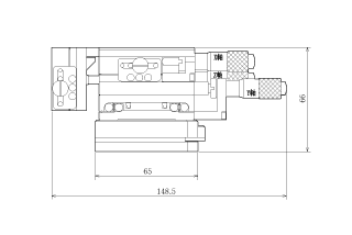
Model AP-1023( Front View )
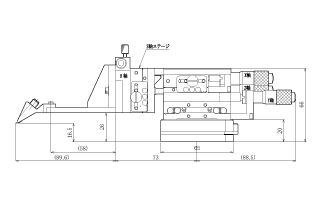
Model AP-1033( Front View )
* Specifications and/or appearance are subject to change without prior notice for further improvement. Please confirm details with our sales department before placing an order.
* All rights reserved. No part of the specification may be reproduced without permission.

